
6. Digitizing Vector Layers
QGIS provides easy-to-use yet very powerful digitizing tools. Digitizing or digitization is a process of encoding map coordinates and attributes in digital form. This allows you to create and edit vector data using various data sources such as text files, paper maps, or satellite imagery. This exercise will guide you through the basic interface of vector digitizing using QGIS.
6.1. Creating a new project
1. Open QGIS and create a new project. In the Menu, select
 New Project.
2. Open Project Properties and click the Coordinate Reference System (CRS) tab. Set the following options.
- Check the Enable ‘on-the-fly’ CRS Transformation.
- In the Coordinate Reference System, choose Projected Coordinate System –> Universal Transverse Mercator –> WGS 84 / UTM Zone 51N.
Note
On the fly CRS transformation allows you to combine various data layers with different reference system into a single map view.
6.2. Loading raster data
1. To load raster data, select
 Add Bing Aerial layer.
Note
A Raster dataset is composed of rows (running across) and columns (running down) of Pixel s (also know as cells). Each pixel represents a geographical region, and the value in that pixel represents some characteristics of that region.
Images with a pixel size covering a small area are called ‘high resolution’ images because it is possible to make out a high degree of detail in the image. Images with a pixel size covering a large area are called ‘low resolution’ images because the amount of detail the images show is low.
Some raster data have two files included. For example, a file with the tif extension is the image and the file with the extension tfw is the world file. World files describe the location, scale and rotation of the map. By adding a world file in any image, GIS applications can read and georeference almost any image. However, the world file does not give the proper coordinate reference system of the raster. More information here. In QGIS, you have to properly set the CRS for raster with world file.
6.3. Loading Vector data
1. Open the following
admin_bnd.shp vector.
2. Zoom to the extent of admin_bnd.shp. Right click on the layer,
select  Zoom to Layer Extent.
3. Create a suitable symbology and color scheme for the layer.
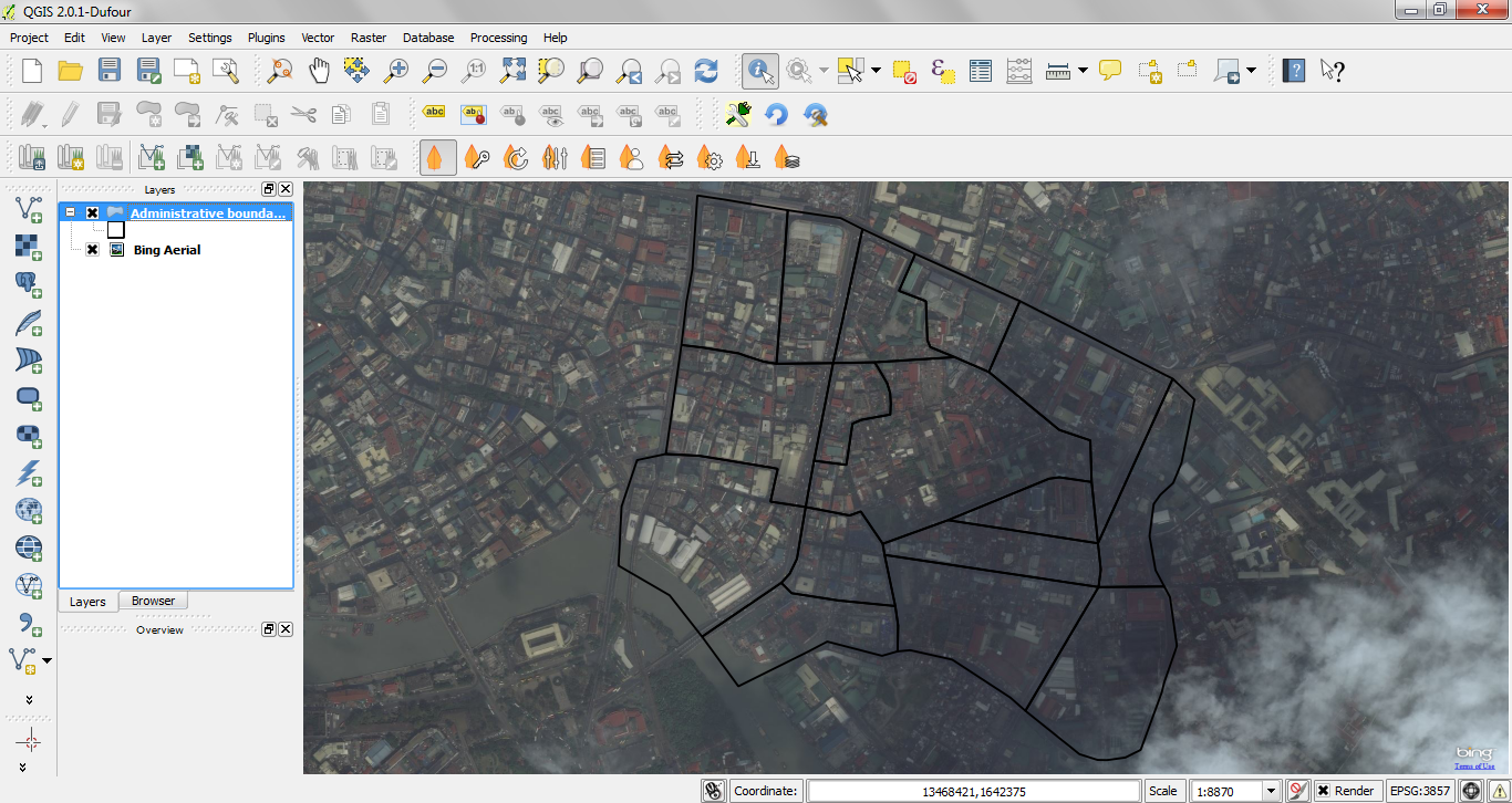
We will use the Bing Aerial layer raster as our primary source for a roads layer.
6.4. Creating a new vector layer
We will now create a new vector layer, to digitize roads. We will use a line layer to represent this data.
1. To create a new vector layer select
New –>
 New Shapefile Layer.
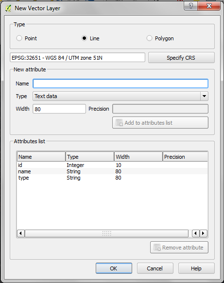
2. In the Type option, choose Line.
3. In the Specify CRS, select WGS 84 / UTM Zone 51N.
4. In the New attribute, add name in the Name field
and choose Text data as the data type. Then, click
Add to attributes list. The newly added attribute field is
added in the list.
5. Add another attribute column. In the New attribute, add type in
the Name field and choose Text data as the data type. Then,
click Add to attributes list.
In the name attribute field, we will encode the name of the feature. In the
type attribute field we encode the type of road (either primary, secondary, residential, etc.).
Click OK.
Tip
Limit field names to a maximum of 10 characters and avoid special characters
(such as &, #, @ { ) and spaces.
6. A new window will appear for the filename and location of the data within your
directory. Use the filename, quiapo_roads.shp.
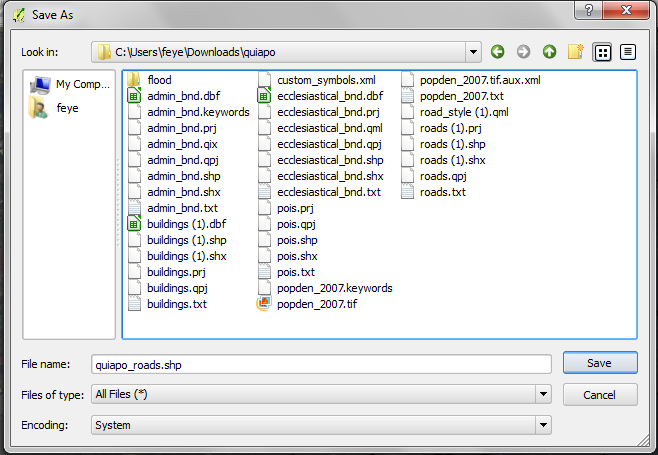
Click Save. You now have a blank roads layer.
6.5. Setting options for digitizing
Before we can begin digitizing, we must set the snapping tolerance to a value that allows us an optimal editing of the vector layer geometries.
Tip
Snapping tolerance is the distance QGIS uses to search for the closest vertex and/or segment you are trying to connect when you set a new vertex or move an existing vertex. If you aren’t within the snap tolerance, QGIS will leave the vertex where you release the mouse button, instead of snapping it to an existing vertex and/or segment.
1. To set the snapping tolerance, select Snapping options. Within the Snapping options window, activate the Enable topological editing by adding a check mark.
2. In the list of layers, add a check mark to the quiapo_roads. This activates
snapping in respective layer. Set the snapping tolerance to 10 map units for
quiapo_roads layer. Select Apply –> OK.
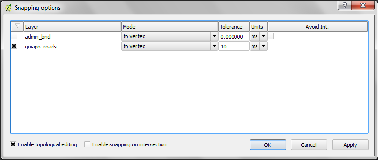
When you start editing the roads layer, new vertices will snap if it is within 10 map units or 10 meters of another vertex.
3. Save your project.
6.6. Digitizing vectors
We will now start digitizing roads.
Note
This process is called heads-up or on-screen digitizing. This is an interactive process, in which a map is created using a previously digitized or scanned information. It is called “heads-up” digitizing because the attention of the user is focused on the screen.
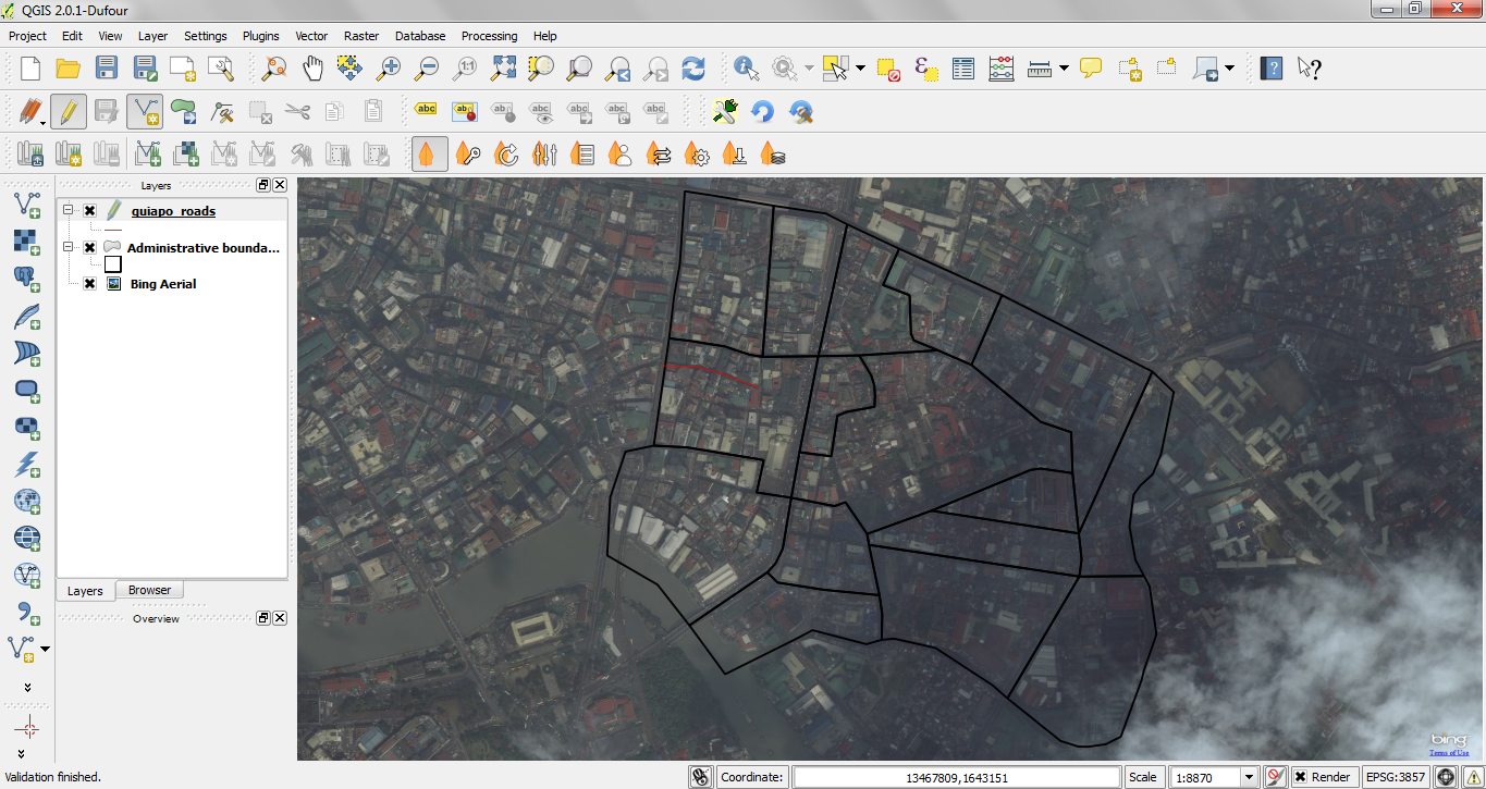
1. Make sure the quiapo_roads and Bing Aerial layers are visible. Click the
checkbox preceding the name of the layer in the Map Legend view to
hide/show layers.
2. Zoom-in to an area, where the roads on the image are visible.
3. Select the quiapo_roads layer, right-click and select  Toggle Editing. Once the layer is in edit mode, additional tool
buttons on the editing toolbar previously greyed-out will become available.
Toggle Editing. Once the layer is in edit mode, additional tool
buttons on the editing toolbar previously greyed-out will become available.
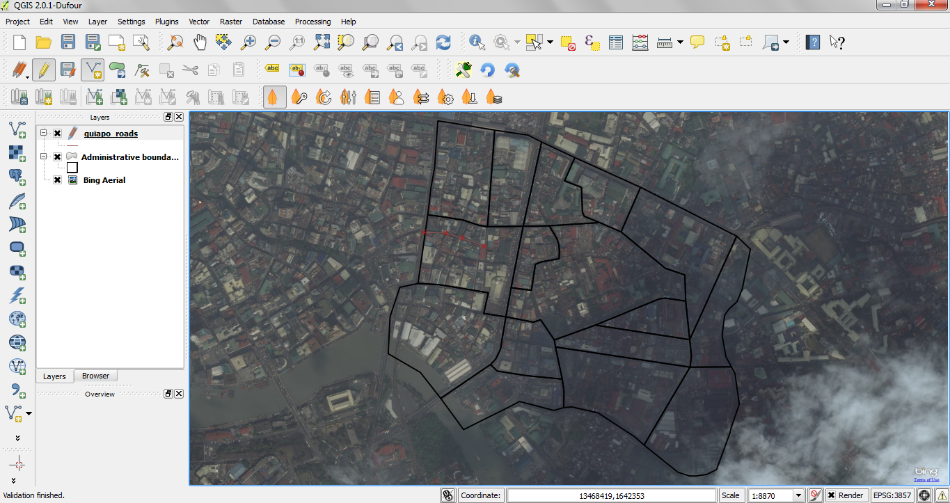
For each feature, you first digitize the geometry, then encode the attributes.
4. To digitize the geometry, click the  Add Feature,
left-click on the map area to create the first point/vertex of your new feature.
Add Feature,
left-click on the map area to create the first point/vertex of your new feature.
For lines and polygons, keep on left-clicking for each additional vertex you wish to capture. When you have finished adding vertices, right-click anywhere on the Map View to confirm you have finished entering the geometry of that feature.
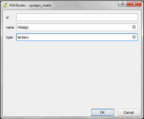
The attribute window will appear, allowing you to enter the information for the
new feature. Add the type of road in the type field and the name of the
feature in the name field.
To save your editing session, Toggle Editing
and click Save.
Tip
In some cases, you will reach the edge of the Map View but you would like to continue adding new vertices. When this happens, use the arrow keys or press the spacebar while using your mouse to pan across the Map View.
The Node Tool
The  Node Tool provides manipulation capabilities of
feature vertices similar to CAD programs. It is possible to simply select multiple
vertices at once and to move, add or delete them all together. The node tool also
works with on-the-fly projection turned on and supports the topological editing
feature. This tool is, unlike other tools in Quantum GIS, persistent, so when some
operation is done, selection stays active for this feature and tool.
Node Tool provides manipulation capabilities of
feature vertices similar to CAD programs. It is possible to simply select multiple
vertices at once and to move, add or delete them all together. The node tool also
works with on-the-fly projection turned on and supports the topological editing
feature. This tool is, unlike other tools in Quantum GIS, persistent, so when some
operation is done, selection stays active for this feature and tool.
Basic operations
Start by activating the Node Tool and selecting some features by clicking on it. Red boxes appear at each vertex of this feature. Functionalities are:
- Selecting vertex: Selecting is easy: just click on vertex and the color of
this vertex will change to blue. When selecting more vertices, the
Shift key can be used to select more vertices. Or the
Ctrlkey can be used to invert selection of vertices: if selected already then it will be unselected and when not selected, the vertex will be selected. More vertices can be selected at once when clicking somewhere outside feature and opening a rectangle where all vertices inside will be selected. Or just click on an edge and both adjacent vertices should be selected. - Adding vertex: Just double click near some edge and a new vertex will appear on the edge near the cursor. Note that the new vertex will appear on one side, not necessarily on the cursor’s position. Move it as necessary.
- Deleting vertex: After selecting vertices for deletion, click the Delete key and vertices will be deleted.
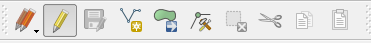
The rest of the basic editing tools are explained below:
- Toggle editing - Enable editing of the
selected vector layer.
 Save Edits - save your editing session in the
currently selected layer. This is different from Saving your project.
Save Edits - save your editing session in the
currently selected layer. This is different from Saving your project. Add Feature - Point - add point features.
- Add Feature - Line - add line features.
 Add Feature - Polygon - add polygon features.
 Move Feature - move location of a selected
feature.
Move Feature - move location of a selected
feature.- Node Tool - activate Node tool functions.
 Delete Selected - delete selected one or
more features.
Delete Selected - delete selected one or
more features. Cut Features - delete a selected feature(s) from
the existing layer and place it on a “spatial clipboard”.
Cut Features - delete a selected feature(s) from
the existing layer and place it on a “spatial clipboard”. Copy Features - place selected feature(s) into
the “spatial clipboard”.
Copy Features - place selected feature(s) into
the “spatial clipboard”. Paste Features - paste feature(s) from the
“spatial clipboard” to the currently selected and editable layer.
Paste Features - paste feature(s) from the
“spatial clipboard” to the currently selected and editable layer.
Full description of the editing tools and other advanced features available in the QGIS User’s Manual.
5. Finish editing the roads layer.
6. Save your project.
Tip
Remember to toggle Toggle Editing off
regularly. This allows you to save your recent changes, and also confirms that
your data source can accept all your changes.